Battery smart bms 48v 200ah lithium battery lifepo4 bms 12v bms active balance
SKU: HT-123622
Lead Time
5-15 days
Shipping
Sea freight, Air freight, Express
Payment
T/T, L/C
Sample
Available
Product details
Product overview
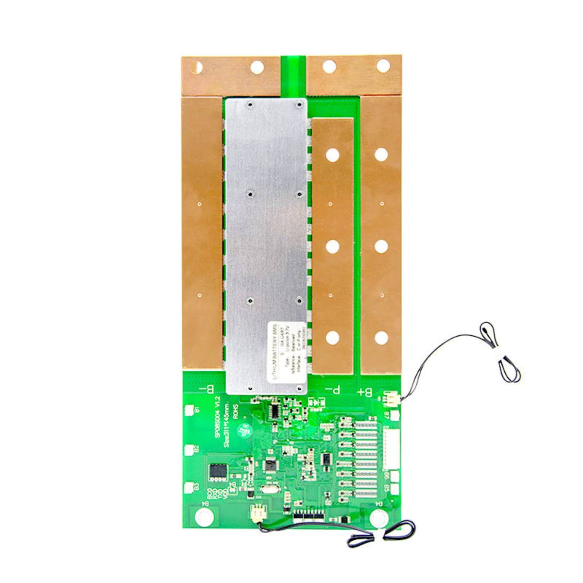
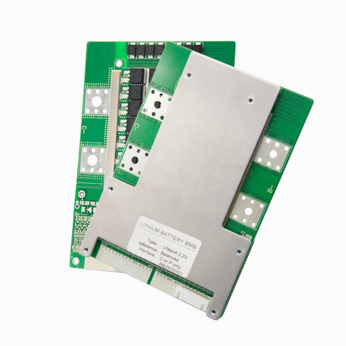
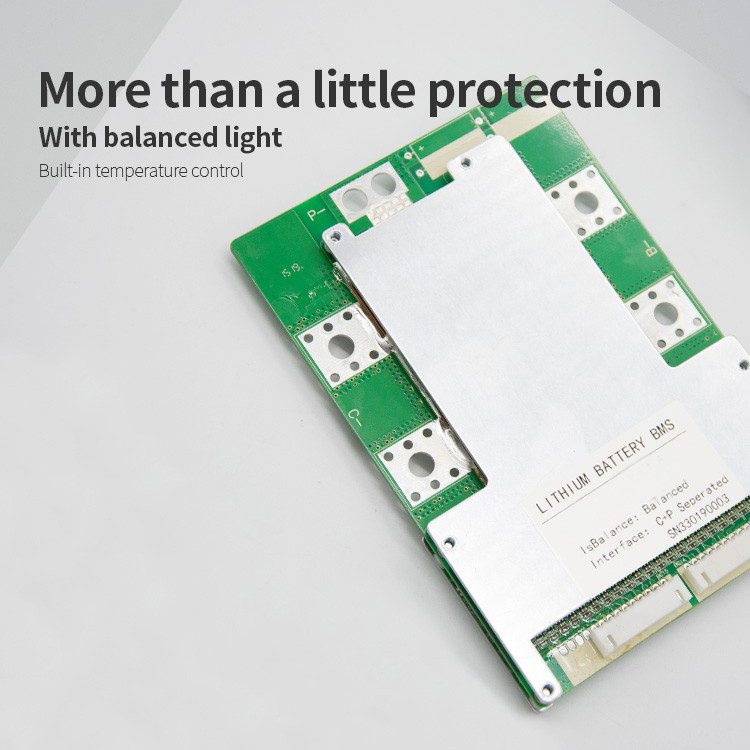
HKIVI 17S-24S 80a BMS for electro-tricycle lithium battery
balance led temperature control hardware bms
|
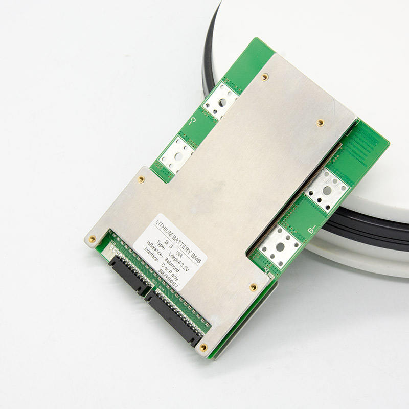
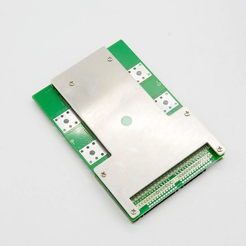
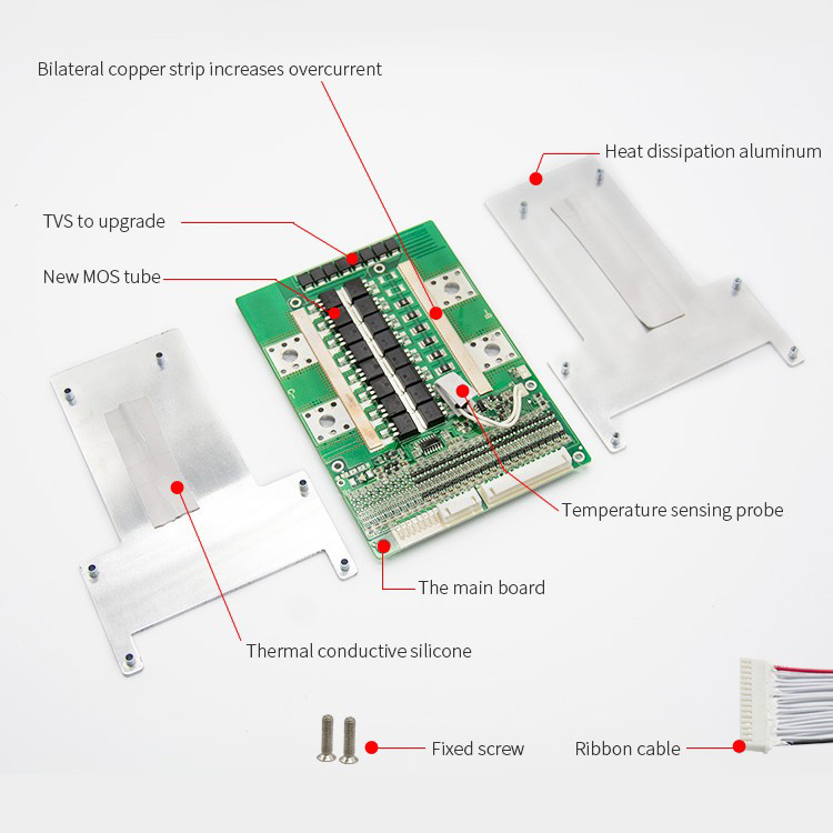
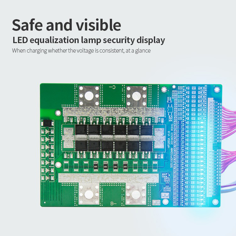
HKIVI-HP28SA is the hardware BMS which designed for battery packs of the inverter, the electric bicycles and the electric motorcycles of batter packs. It can be applied to lithium batteries with different chemical properties , such as lithium ion, Li-polymer. Lithium iron phosphate, etc. The protection board has strong loading capacity and the maximum continuous discharge current can reach 80 A. ●17-24 cell series protection ● Various protection functions for charging and discharge ● Discharge overcurrent, short circuit protection functional process of hardware ● reserves the discharge control switch and the position of discharge temperature protection, ●Very low static current consumption ● Containing charging equalization function |

| Application | |||
| Battery series | Battery Rated voltage | Battery series | Battery Rated Voltage |
| 17 | 3.6V/3.7V(60V) |
24 |
3.6V/3.7V(72V) |
| 3.2V(60V) |
|||
|
Protection function description Overcharge protection: when the battery is under the charging state, the voltage keeps going up. When the protection board detects that the voltage of any cell is higher than the overcharge protection value, the protection board will start timing immediately. overcharge protection delay, the protection board will turn off the charging MOS tube, at that time, it can not be charged. Overcharge protection recovery: After the overvoltage protection appears on the protection board, the battery voltage will going down under the static or discharge state of the battery. When the protection board detects that each voltage is lower than the recovery voltage of the overcharge protection, the protection board will output a signal and turn on the MOS tube to charge. Over-discharge protection: When the battery is under the discharge state, the voltage keeps going down. When the protection board detects that the voltage of any cell is lower than the overcharge protection value, the protection board will start timing immediately. reach the over discharge protection delay, the output signal of the protection board will turn off the discharge MOS tube, the load lock circuit will work, but, it cannot discharge at this time. Over discharge protection recovery: After the over discharge protection appears on the protection board, the battery voltage will go up under the static or discharge state of the battery. When the protection board detects that each voltage is higher than the recovery voltage of the over discharge At this time, disconnect the load or charge, the protection board will output a signal and turn on the charging MOS tube to charge. Overcurrent protection: When the battery is under the static or discharge state, the current suddenly increases. When the protection board detects that the current reaches the overcurrent protection value, the protection board will start timing at that time. reaches the overcurrent protection delay time, the output signal of the protection board will turn off the discharge MOS tube, and the load lock circuit will work. Overcurrent protection recovery: After the drain overcurrent protection appears on the protection board, the discharge MOS tube is turned off, and the current in the loop becomes 0. At this time, the load is disconnected or charged, the output signal of the protection board will turn on discharge MOS tube to discharge. |
| Functions | Test items | specification | Unit | ||
| Min | Type | Max | |||
| Operating current | recharging current | - | - | 80 | A |
| Discharging current | - | - | 80 | A | |
| Charging protection | Charger voltage (CC-CV) lifepo4 | Battery series *3.6 | V | ||
| Charger voltage (CC-CV) Li-ion | Battery series *4.2 | V | |||
| Over-charge protection voltage lifepo4 | 3.600 | 3.650 | 3.700 | V | |
| Over-charge protection voltage Li-ion | 4.220 | 4.250 | 4.280 | V | |
| Over-charge protection delay time | 500 | 1000 | 1500 | mS | |
| Over-charge protection recovery voltage lifepo4 | 3.400 | 3.450 | 3.500 | V | |
| Over-charge protection recovery voltage Li-ion | 4.140 | 4.180 | 4.230 | V | |
Discharge protection |
Over-discharge protection voltage lifepo4 |
2.400 | 2.500 | 2.600 | V |
| Over-discharge protection voltage Li-ion |
2.700 | 2.800 | 2.900 | V | |
| Over-discharge protection delay time |
50 | 100 | 200 | V | |
| Over-discharge protection recovery voltage lifepo4 |
2.900 | 3.000 | 3.100 | mS | |
| Over-discharge protection recovery voltage Li-ion |
2.800 | 2.900 | 3.000 | V | |
| Over-discharge protection recovery condition |
Disconnect load or Charging activation | V | |||
Overcurrent protection |
Charging overcurrent protection value | - | A | ||
| Charging overcurrent delay | - | mS | |||
| Charging release adjustment | - | ||||
| Discharge overcurrent 1 protection current value | 280 | 300 | 320 | A | |
| Discharge overcurrent 1 protection delay | 50 | 100 | 200 | mS | |
| Discharge overcurrent protection recovery condition | Disconnect load or Charging activation |
||||
Short circuit protection |
Short circuit protection delay time |
100 | 200 | 300 | uS |
| Short circuit protection recovery |
Disconnect load | ||||
Balanced function |
Balanced turn-on voltage lifepo4 | 3.400 |
3.450 |
3.500 |
V |
| Balanced turn-on voltage li-ion | 4.170 |
4.190 |
4.220 |
V |
|
| Balanced turn-on voltage li-ion | 20 |
30 |
mA |
||
Temperature protection(internally installed) |
temperature protection value | - | 75 | - | ℃ |
| temperature protection release value | - | 53 | - | ℃ |
|
| Internal resistance |
Discharge loop internal resistance | - | 10 | 20 | mR |
| Self-consuming |
Operating mode | - | 20 | 50 | uA |
| Working humidity |
Normal operating range | -20 | - | 70 | ℃ |
| Storage temperature |
Humidity<90%, No condensation | -40 | - | 85 | ℃ |
| Protection board size |
L*W*H | 150*102*15 |
mm | ||
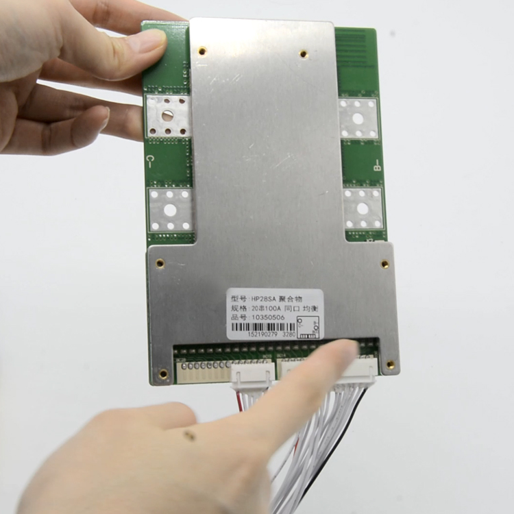
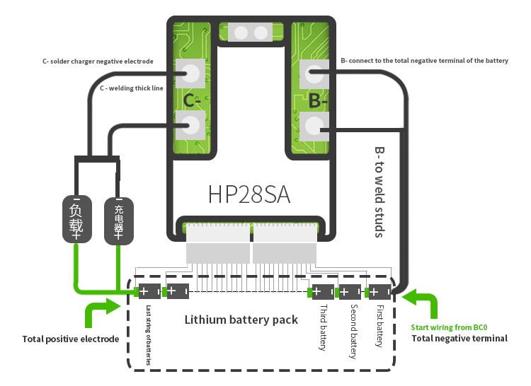
Wiring diagram of same port protection board
Only a number of welding method as an example,
the same analogy toother number of protection plate wiring methods
| port | Description |
| C | Charge and discharge negative poles |
| B- | Connect the first string of negative pole of the battery pack, that is, the total negative pole of the battery pack |
| BC0 | Connect the first string of negative pole of the battery pack |
| BC1 | Connect the first string of positive pole of the battery pack |
| BC2 | Connect the second string of positive pole of the battery pack |
| BC3 | Connect the 3rd string of positive pole of the battery pack |
| BC4 | Connect the 4rd string of positive pole of the battery pack |
| And so on, all the way to the end | |
| When assembling the wiring, weld the cable and the cell correctly, connect the B- of the PCM with the total negative pole of the cell, and then insert the cable into the needle base on the PCM. (Note: different connection modes for different strings, and different connection modes for the same port) |
Similar products
View all →

#p-17195COCH® DLY-10CW1 4.5in Handheld and Horizontal Multifunctional Lithium Battery Band Saw
Quote on request